|
My 1989 Lotus Esprit Turbo (Non-SE)

I may not be impartial, but I think it is the most beautiful car in the
world.
Background
Window Motors
Window Motor Relay Mod
Fuses & Relays
The Speedo
Adjusting the Timing Belt
The Alternator
Headlight Motors
Radiator Vent Plug
Radiator hose from intake to water
pump (thermostat)
Welding the exhaust manifold
Esprit Stainless Exhaust
Manifold
Valentine One Mounting
The Dr.Hess 50 minute Turbo Removal Method
Battery Tender
Trunk Latch Peace Of Mind
HKS SSQV BOV
Parts Substitutions
Background
Well, I was getting tired of driving beaters all the time. My daily
driver has 237K miles on it (Toyota Truck). My back-up daily driver has
248K miles on it (Toyota Truck). The Seven was coming along, but still had
(has) a ways to go and really isn't all that practical (regardless of what Phil
says) especially with no roof/top planned. So, I started to thinking about
some new wheels. But what to get? My wife said "You always buy
something practical. Why don't you get what you really want?"
Well, Project 3SGTE Europa was calling, but I really didn't need to start
another major automotive project without finishing the one I am on now. I
started seriously thinking about a SC400, that V8 being about the best I have
ever driven. But still, it isn't really what I wanted.
I sort of figured that whatever I wound up with I would have to haul home, so
I got the '86 Truck in good towing shape and bought a flat bed dove tail
trailer.
So, I started looking at Esprits. Amazing what you can find on eBay.
Bought one with a Buy-It-Now for a fair price, loaded up the truck and headed to
San Jose, CA. Three days later, the Crystal Princess was sitting on the
trailer behind the little red truck and we were headed back to Arkansas. I
decided to tow it because: I have owned a Lotus before. It is used,
English and has lots of unknowns. I figured better safe towing it across
1800 miles than broke down in Bumfuq New Mexico looking for a water pump for a
910 engine.
Now, towing a 2700 lb car on a 1500 lb trailer with a 4 cylinder 22R Toyota
Truck is a bit of an adventure in itself. Uphill was
"challenging" but we would just tuck in with the 18 wheelers and do
the best we could. Through the desert we would also have to turn the AC
off and the heater on high on the hills to keep the temp down. I think if
I went with a genuine Toyota fan clutch, that would help, and I have heard that
a 22RTE radiator is bigger and bolts in. We'll have to see. Gas
milage was 19 MPG under load, 21 with just the trailer. Not too bad,
huh? Truck had 248K miles on it when we got home. Two days leter
when I took it to work, the left rear wheel bearing went out. What timing.
Window Motors
Guess what? Lotus did not make window motors!! Yes, it is true.
They went to the parking lot and pulled someone's Jag apart and designed the
windows around that. So, what that means is that when your window motor
gives up, you can replace it with one from a Jag for a fraction of the cost of a
new or rebuilt. I bought one extra for each side off eBay. Paid $15
for one and $1 for the other plus shipping. Rebuilt out of Florida is
about $250 ea. The important thing to realize is that there are several
different types of Jag window motor out there. The Esprit has the skinny
flat one instead of the big round one, and the Esprit has an 8 tooth gear on the
gear box part. Some Jag's have 10 teeth. Also, a Left Esprit window
motor is the same as the Front Right Jag motor, and vice versa. The actual
motor part is all the same, but the gear box part bolted to the motor part is a
mirror image on each side. Different year Jag motors will work, but if you
want a drop in replacement maybe with the regulator too, try these: 88-91 Vandem Plas, 81-87 XJ6, 87-90 XJS Coupe.
There are some good tutorials out there on taking the door apart and getting to
the motors, so I'll leave that alone. Check the EspritFactFile.
Here
is my eBay search for Jag window motors. I know these things because I
had to fix both my motors. The driver's side responded well to a thorough
cleaning and lube, but the passenger side was toast. The little brush
holder melted. I replaced it with a motor from a Chevy truck, which I had
to do a little Dremmel tool work on to get to fit with the original gear
box. Seems that English Delco used a different brush holder than US Delco.
More details: My Chevy truck replacement motor went to the same fate as
the original one. Toasted brush holder. So, there are Delco and
Bosch Jag window motors. The Delco are the ones we need as a drop in, but
the Bosch can be made to work. Problem is the Bosch, as the one from the
88 XJ6 I bought off eBay, is almost the right one, but the little spacer
thingies that the bolts go into are too short. So, I made some adapter
spacers on my lathe out of some brass I had around to hold the motor off to just
the right spacing. If anyone is interested, I'll send you a drawing of the
spacers and you can make them yourself or have them made.
Why did my replacement die? I suspect low voltage at the motor due to
the switch arrangement. I am working on a relay to reside inside the door
and utilize the +12V from the lighter. Total cost should be about $40 for
the two relays from O'Reilly's auto parts and a couple of diodes from Radio
Shack.
Window Motor Relay Mod
Here is a scan of a
schematic I drew up to use two commonly available relays to run a window
motor without putting a load on the switch. Part of the problem is the
switch gets fried by the current draw of the motor. So, if you use relays
as the later cars have, the switch should last a long time. In theory
anyway. So I drew up and tested the schematic. I haven't installed
it, so it is technicall still a WIP (Work In Progress) but electrically it
works. The diodes are just any standard silicone diode such as a 1N4004
from Radio Shack or salvaged from just about any piece of junk
electronics. There isn't much current through them, we just use them for
the logic. The input wires on the left are the wires that originally went
to the motor. They now just drive the relays. The battery symbol
represents a source of 12V. I was thinking of using the lighter supply,
but never got that far. The 12V can be on all the time, it won't drain the
battery and the windows still won't work without the key on. The other
choice for the +12v would be splicing into the line going to the window
switch. The relays are Borg Warner R802 DPST 12V, 20A contacts and were
$18 each at O'Reilley's. I wanted to use cheaper ones, but that was all I
could find easily and they should be available everywhere. I superglued
the two together. Wires to the relay coils can be small, like 20ga, or
22ga as there isn't much current there. The rest of the wires should be
12ga or 14ga. When the + voltage is applied to one wire and - to the other
from the OEM switch, one relay will energize and the proper polarity will be
sent to the motor. When the polarity is reversed fromt he switch to the
relay pairs, the other relay will energize and the opposite polarity will go to
the motor.
Others have made relays for their window motors, but I didn't look at what
they did. I just started from a clean sheet and this is what I came up
with. If it is identical to someone else's, well, I guess we think
alike. This was just how I figured to do it without modifying anything
very much. My windows are working OK right now (knock on wood) so I never
got around to installing it, and because of the aftermarket window controller I
have, I would have to do some rewiring and go back to stock first to get this to
work properly. It seems the aftermarket controller has a current sensor in
it and if the current is too low, it will turn off the motor. Putting my
relays in drops the current seen by the switch/aftermarket controller to next to
nothing, so the controller freaks out. With a stock setup going through
the switches, this wouldn't be a problem.
Fuses & Relays
Cut this out and tape it with some clear package tape to the underside of
your front relay cover:
Fuses&Relays
You may have to "save as" the image, then open it in an image
editor and print from there. The size is set to 3-3/4" wide, which just
fits under the cover, but I don't think IE will print it out correctly. You can
add the image to a MS Word document and play with the size until it is
3-3/4" wide, then print it. Even though it looks a little fuzzy in an image
editor or just in IE, when printed out at the correct size on a laser
printer it is quite readable.
New Medical Term: LNS: Lotus Neck Syndrome. A spasm of the right
sterno-clido-mastoid muscle caused by prolonged time in the Lotus Position.
Hey, why don't the English put hinges on the dashboard? I mean, is it some
kind of eternal English optimism? Like this will be the vehicle that will
never need someone under the dash fixing the electrics. Kinda like yeah, Hitler
only wants Poland, then he will stop. Here is another one: We'll make guns
illegal, then people won't shoot each other and crime will go down. Really
bizarre English optimism.
The Speedo:

So, like most of this vintage, my odometer went out at about 50K miles.
So, what to do? Get it repaired for $150 and have a repaired speedo good
for who knows how long, or just replace it with a better one that I might
actually be able to see? Well, on my last trip to Sturgis, I stopped at
the Harley dealer in Souix Falls, S.D., and was talking to the parts guy about
the last year when I stopped there to buy yet another speedo cable, and he told
me of Dakota Digital, who make
speedos for bikes, cars, etc. They even had a display set up at Sturgis,
so I looked at their stuff then. I decided to just put one of their units
in and dump the VDO POS all together. A talk with their tech support guy
and it looked like the ODYR-01-1
was what I needed. Not wanting to mess with the vehicle speed sensor (VSS),
I opted for the speedometer cable sender adapter thingie for an extra 20 or so
and also had them set the mileage to what my now dead odometer was
(another 20). About $240 with shipping. The main PITA is that the
hole in the dash/VDO guage is 4-1/8" and the new speedo is
4-3/8".
I took the instrument pod off, which is 4 bolts, 3 plugs, one speedo cable
and about 5 minutes on the 89 non-SE. Really easy, and approaching that
flip-top dash concept. Then about an hour with a Dremel brand moto-tool
and an air die grinder and the hole was just right. Wiring was easy:
Switched +12v and ground from the dead clock plug, night instrument lights (dims
the speedo display) from the no longer needed VDO speedo light bulb plug, and
two wires (power and signal) to the cable sender adapter thingie. The
cable sender adapter thingie didn't quit fit the end of the speedo cable, but I
had anticipated this and the Dakota Digital guys said that most people just wrap
tape around their sender until it fits the nut thing on the cable. Did
that. Calibration is easy. You hold the button in, start the
car, release the button, push it when AUTO shows up, drive exactly 1 mile, push
the button again and you are calibrated. I measured off 1 mile by Camry
and by map to confirm, and calibrated it that way.
Problem: The speedo cable does not move at a constant rate. It
binds a little, so it moves fast/slow/fast/slow, etc. At a steady rate,
this is OK, but when accelerating, the digital display would jump anywhere from
+/- 5MPH to +/-20MPH. This kinda makes it about useless, especially in the
cold. It is worse when the weather is cold, as the grease in the cable
gets thicker and exacerbates the problem. So, what to do? Well, a
look through the schematic showed that the ECM has a VSS input after all.
I didn't look into it too thoroughly, as I didn't want to mess with the ECM
wiring and with running the extra wire. As the sender thingie was not
working out, taping into the VSS started to look better and better. The PO
had an early 90's cell phone in the car, which I removed, but I left the wires
in place. There was a head unit in the cabin, a shielded data cable going
to the boot and a transceiver back there. So, I just used one of the wires
in that cable. I tapped into the VSS at the ECM. There are two wires
that run to the VSS from the ECM. They are purple and yellow and are
twisted together and go to the middle plug. Lotus (English) wiring has purple as in
general being fused +12v, so I figured the yellow one would be the one I
needed. I tapped into the wire near the ECM plug. Only the signal
wire from the speedo was needed. After
re-calibrating it, it is now working great. Rock steady Remember this is on a 89
Non-SE. SE's have the different colors and II think both are
shielded. They are also on a different plug. Mark Wiens suggests an
undocumented output pin used for later models (S4s' ) at J2-B8.
A nice thing about this speedo is that you can actually see the difference
between 70 and 80 MPH. And you can actually see the thing when it starts
to wind up there. Actually, you can see it all the time, which is kinda
nice. It also gives you 0-60 times, top speed, has a trip and service odometer and is
in general, pretty nice. I am happy with it. I do now have an extra
sender thingie, if anyone wants it.
Adjusting the timing belt:
Here is a thread from Tim Engle:
--- In turboesprit@yahoogroups.com, "Tim Engel" <tengel@m...> wrote:
> From: "Dr. Hess" <hess@f...>
> To: <turboesprit@yahoogroups.com>
> Sent: Sunday, April 11, 2004 9:48 PM
> Subject: [turboesprit] Timing Belt Tensioner
> >
>
> > Is there some secret to getting to the 17mm nyloc nut on the timing
> > belt tensioner? I can't seem to get a combination wrench or a socket
> > on it. Do all the accessory belts have to come off so you can get to
> > it? Or is there some secret wrench that "just" fits?
> >
> > And how can you see the timing marks without a mirror from below?
> > Damned if I can see them at all from the top.
> >
> > I need to adjust the timing belt tension. It is at 25 on the Kricket
> > scale.
>
>
>
> Dr.Hess,
>
> You will need to clear a path first, then use a 17mm open end wrench on the
> Nyloc nut. A socket will work for initially loosening the nut; however,
> when you get around to tightening things up again, a socket usually
> interferes with the 19mm wrench that's required for the hex on the eccentric
> adjuster. Install the 19mm as straight up as you can on the eccentric hex,
> then go after the 17mm with the open end wrench at an angle to clear the 19.
> A bent 17mm would be good if you have one.
>
> I think it's easier in the long run to remove the alternator, it's belt,
> tension brace and triangle bracket. And removing the alternator is easier
> (ie, possible) if you remove the intake plenum and air filter box first.
> Then you have a pretty clear shot at the tensioner from above without
> disturbing the other two V-belts or their pulleys from below. It sounds
> like a lot of work, but it's more work if you try to avoid the work.
> Heck, you'll waste more time thinking about alternatives than it will take
> to yank the airbox and plenum. Just suck up and do it, and you'll be done
> much faster in the long run.
>
> Be sure to disconnect the battery before removing the alternator.
>
> If you leave enough tension on the Nyloc to pinch the eccentric a bit, you
> can still adjust the eccentric with one wrench, yet it will stay where you
> leave it when you let go. However, if you attempt to tighten the Nyloc
> with one wrench, the friction drag will pull the eccentric around and
> change the tension setting. So one-wrench it while adjusting the belt
> tension with some Nylon tension, then use two opposing wrenches to tighten
> the Nyloc.
>
> Be certain that you adjust the belt tension by turning the eccentric into
> the belt counter-clockwise as viewed looking at the front of the engine.
> That will take the eccentric down around the bottom of it's orbit and up
> into the belt. Up over the top of the orbit and down against the belt is
> incorrect.
>
> With the eccentric-style tensioner, very little movement makes a big
> difference in belt tension. Just a nudge is good for a quick 10 lbs.
>
> I just did the job yesterday, so I know your pain.
> Have fun,
> Tim Engel
After removing the plenum, tube thing where you guys have a charge cooler and alternator, I could actually get to the
tensioner. I took a "Sears" brand 19mm combination wrench from my "Junk Tools" bucket (couldn't find one at my favorite pawn shop in their 25 cent bins) and ground the box end down to about 3/8" or so thick. With this, I could hold the adjuster in the correct position and get a 17mm combination wrench on the nyloc nut.
I found the 17mm socket and short extension I dropped down the front of the motor. It was hiding behind/under a hose. I think the fairies were
f*(#ing with me, as I must have looked for about 2 hours before I found it and I am sure I looked several times where I eventually found it. I am glad I found it, as it made me kinda uncomfortable leaving a rather large hunk of metal floating around an open timing belt on an interferance motor.
Oh, and I was using the Krickit guage wrong. I didn't have the little lip on the edge. So I was running with less than 25 lbs of tension on the
guage. Probably around 10. Guess it was time to adjust it, huh?
The Alternator
Well, the Valeo alternator started to die at about 55K miles. Actually,
I think it was just the voltage regulator. Started to drip black ooze onto the
AC compressor, and when the Ac compressor or headlights came on, the voltage in
the system would drop to the point that the Valentine One was rebooting. I
replaced it with a Bosch ($80 + tax). Ed's
page has just about everything you need to know, except what to ask
for at the parts house: 1987 BMW 325i. About all I could add to Ed's
writeup is that the bolt I used when fabbing a new hold down bolt was a 90mm
long 8mm x 1.0mm (couldn't find a 1.25 TP in that length) that I got from Ace
Hardware, I had to grind down the original half moon key thing because the Bosh
keyway wasn't as deep as the Valeo, and I took a Dremel brand Moto-tool to the
casing when I "clocked" the back. Didn't want to turn
otherwise. I didn't have to take much off, just clean it up a little so
the ears would clear. Oh, and I used a hand operated impact screwdriver to
break loose the screws holding the thing together and I shortened the screws a
little after it was all back together. Put the hold down bolt in first,
then put the pivot bolt in. And the belt was a tight fit. I put it
over the alternator pulley then partially over the harmonic balancer pulley and
turned the motor over by hand to get it on the rest of the way.
In summary: Remove 4 long screws, dremel interfering housing areas,
rotate (clock) back part, replace 4 screws, cut at least the 2 left side screws
down so they don't stick out as much, remove pulley/fan/spacers from old POS
alternator, Place: 1 thin spacer, fan, grind down woodruff key on flat
edge until pulley slips over, put woodruff key and pulley on, bore out fat
spacer until it fits over bolt, place fat spacer over bolt, nut. Get longer bolt
for hold-down or fab a new piece, cut off spade terminal connector end of small
wire, replace end with eye, put on D+ terminal, place big wire on B+ terminal,
put RF noise supression capacitor on one of the long bolts on the back and lock
down with nut, other end goes to spade terminal.
Funny thing, though: My V1 was still rebooting after a big load change
like headlights, etc. I went through the schematics in the manual and
figured it had to be either the central connection that powers everything at the
starter solenoid or at the bonnet end junction box point. So I started at
the starter end and what do you know? The nut holding all the wires on was
loose. The cable from the solenoid to the alternator also looked a bit
iffy, corroded and burnt a bit, so I replaced it with some wire I had laying
around that did the exact same job from the 4AGE 20 valve. Voltage
at my volt meter in the dash now reads a steady 13.8-ish and the V1 is rock
steady. I am still glad I ditched the Valeo. Black goo dripping from
a piece of electronics can never be a good thing.
Headlight Motors
I rebuilt my headlight motors with a kit from www.top-downsolutions.com.
Part number 209280. There are several out there, but this one has
everything you need, including new gaskets, white lithium grease and some extra
nuts and bolts in case you destroy the screws when you take it apart. Sanj
has a pictorial guide here.
I would add that I did not remove the bolt as shown in picture T0003689.jpg but instead removed the screw and nut on the motor side of the
bracket. The bolt shown has a nut mounted in typical Lotus fashion, that
is, not captive and in a place that you virtually can't get to it. Taking
the phillips head screw out was much easier. Unless you have arms about 2
inches across and 4 ft long, that is. The reason I rebuilt them is that my
headlight pods were bouncing a bit when on the road. This was kinda
irritating and the right one especially would droop down eventually. When
I pulled them apart, the little white button things were intact and not like
grated parmesan cheese like others have found, and really showed little
wear. But, since I had bought the kit and gone through the trouble of
taking the first motor out and apart, I went ahead and did the kits to both of
them. Well, it cured my bouncing headlights and I am quite pleased with
it.
Radiator Vent Plug
Well, after changing my radiator fluid, I developed a leak at the radiator
vent plug (located near the left front tire). The threads were
stripped. I pulled and pulled trying to get the thing out until the part
inside broke, falling back into the radiator, so I pulled the lower hose and
flushed it out. Fun fun fun. Then I found that the inside the
radiator part is threaded too, so if you want to remove it, you unscrew it until
it pulls up, then pull up some more and unscrew it some more and it will come
out. I replaced it with a nylon bolt from the Racer's Friend, Ace Hardware
Store, of 3/8" x 16TPI. Not that this is not a metric part.
Having an engine lathe, I bored a small hole about half way through, then
drilled a hole across the threads and through the central hole, thus providing a
easy vent method, but if you dont' want to to that far and just take the solid
bolt out and put it back, that will work too.
Radiator hose
from intake to water pump (thermostat)
I used 5.5" of Gates 24022, which is their universal radiator straight hose in 1-3/8" and two new clamps. Did not have to pull the intake manifold.
Notes:
I put a piece of foam rubber (cut from a hospital matress, actually) in the trunk behind the front trunk wall. Great for saving the knees while you are in the trunk laying over the motor. I cut a piece of 2x4 to fit across the top of the motor between the sides where the cover usually rides. This is great for leaning on without having to worry about leaning on the intake manifold and risking breaking that (a bad thing). Disconnect negative lead to battery as you have to work around the alternator with metal tools. I could get to the rear clamp by using a 1/4" drive socket with a long wobble extension from near the alternator. A mirror on a stick is real handy. Remove the bolt holding down all the sensor ground leads and the vacuum hose and tie it all out of the way. Cut off old hose and either deal with the mess as the antifreeze comes out or drain off the antifreeze first. Put some lube on the inside of the new hose. Slide back end in as far as it will go. Put 2 clamps on. Push front end down hard with a screw driver, pliers handle, whatever until the bottom of the hose lip is over the flange. With a small screw driver and a lot of hand force on the hose, pull the hose up over the top of the flange. Tighten clamps. Replace ground bolt and vacuum hose. Refill with fluid. Connect battery.
Welding the exhaust manifold
When I welded my exhaust manifold, this is what I did:
* ID each crack (3 or 4) and clean with a wire brush
* Drill a 1/8" hole all the way through at the end of each crack to stop it from propigating
* Grind a V down into the cracks, not all the way through.
* Preheat the manifold to 400 degrees F in my oven
* Weld up with nickle welding rod (expensive stuff, like $22/lb) with my AC stick welder
* Post heat back to 400F, turn oven off and let cool down overnight (I have an oven in my shop just for such tasks)
* Sand blast the slag off the inside of the welds
* "Hole match" the manifold by drilling/grinding out each bolt hole to match the head stud pattern so the manifold goes on without being under stress
Just the welding and prep was a lot of work, not to mention getting the damn thing off and on. Cast iron is not the easiest stuff to make stick. I am not a professional welder, but from the research I did, this seems to be how the pro's do it when they want it done right. As you can imagine, just the process I described took a full day to do. If I just took it down to a shop, I seriously doubt they would have gone through all that trouble. They probably would have just heated it up with a torch, hit it with the nickle rod and said, "There you go. No guarantees."
Update: Of the four cracks in the manifold, three held. One
failed next to the weld, which usually implies needing more post welding heat
treating. If I were to weld it again, I would add a step where I would
heat each weld and surrounding areas with my big rose bud torch tip to a red
color and then stick it in the oven overnight.
Which brings us to My:
Esprit Stainless Steel
Exhaust Manifold
Not wanting to spend a grand on another cast manifold which some say works
and some say will still crack on you, and after having successfully made one for
the seven, I decided to build my own. I did that CAD work on the flanges
and had them water jet cut out of 1/2" 304. I used schedule 40 304
pipe. I built a jig, cut and fit all the pipe and tacked it together then
had my Chicken Processing Manufacturer plant (great source for stainless work)
TIG it up. It was a lot of work. Here are some pics: WIP1
WIP2 WIP3
Tacked1 Tacked2
Tacked3 Tacked4
Done1 Done2
Done3
It has been holding up well. When I built it and before I put it on,
I offered to have it duplicated, but the cost would have been one large, and I
had no takers. Now that it is on, I can't get it duplicated because
the shop needs one to look at. It has to be just right or you will never
get it in there. You snooze, you lose. If anyone is interested, I
can provide the flanges and you are on your own after that.
Valentine One Mounting
I took a piece of 16 ga stainless and cut/bent it into the proper
shape (use some paper or stiff thin cardboard for a pattern) and put
that under the mount for the rear view mirror. The mirror screws
hold it up. The distal end of the mount has a hole in it. Through
this hole is a bolt that attaches the detector part of the visor
mount (visor clamp removed). The detector then slides into the mount
which is bolted to the metal (painted black) which is screwed to the
head liner thingie. For the wiring, I got some very thin phone
line. It is flat, but all I had laying around the house was off
white. I painted this black at the end and put a RJ11 on it. This
fits up behind the headliner and runs down the passenger side A
piller. I could push it along the edge of the A piller pad thing so
I didn't have to take it off. Then the wire runs under the dash to
the Valentine power thingie which is spliced in to a switched wire.
I thought about getting a remote and mounting it over the steering
column, but it really works out well this way. Just glance up at the
rear view mirror and you can see how many thugs are trying to rob
you. You can hit the silence button easily. Took an afternoon to
make. I used stainless because that is what I have laying around. A
piece of 16ga carbon steel would work fine as well. I used some VHT
black paint and baked it in my shop oven. Here
is a pic:
The Dr.Hess 50 minute Turbo Removal
Method:
Jack up back of car, place on jackstands.
Remove trunk (10mm head bolts under carpet, 4mm allen screws at the top.
Remove vacuum lines to airbox and throttle actuator. Mark/draw picture if this
is your first time. Pivot trunk around still connected wires and place on top of
engine.
Remove left rear wheel.
Unbolt (3ea, 17mm) downpipe. Put a block of wood between it and the shock or
frame to hold it up out of the way.
Remove intake $150 dryer hose from turbo, bend out of the way.
Unbend the locktabs on turbo. Big screwdriver and a hammer are pretty handy.
Remove hoses: Oil feed, oil drain (bunch of long extensions), water feed,
water drain. Plug water lines with a 3/8" bolt and tighten the hose clamps
on them. Have these plugs ready to go when you pull the lines off so you don't
loose a bunch of your expensive Toyota red coolant. Cover oil line ends with
aluminum foil.
Remove turbo nuts. If it has been on a while, some penetrating oil may be
necessary. I use a selection of combination wrenches including a Stanley stubby
and Craftsman. I can get a full size Craftsman box end on the right front one if
I'm lucky and the lock tab is all the way out of the way. Right rear is easy
with a socket wrench. Left side takes the stubby open end once they are broke
loose with the full size open end. You will likely have to raise the turbo up to
undo the last part of the nuts on the left, so have the right side off by that
point. You will also have to keep propping up the downpipe as it tends to get in
the way.
Pull turbo off manifold.
Place on bench, cover exhaust manifold opening with foil, note time for the
record. I think that's about it.
Battery Tender
I bought this battery tender at HF: http://www.harborfreight.com/cpi/ctaf/Displayitem.taf?itemnumber=42292
Which is called AUTOMATIC BATTERY FLOAT CHARGER. It goes on sale for half
price occasionally. It is not a battery charger, but a keeper that just replaces
what is normally lost to internal resistance, small drains, etc. As has been
said, the Esprit is a battery killing machine. I have managed to get my losses
down to 50 milliamps, but that is it. I have some more theories on where that is
going, but haven’t pursued them. Hooking the tender up used to be a minor
PITA. Popping the trunk, hooking the alligator clips up, etc. So, what I did was
to buy two sets of trailer light connections and a magnetic trailer light wire
holder at Wal*Mart, an inline fuse holder, 3 amp fuse and some heat shrink tube
(Radio Shack). Ground wire goes straight to the negative terminal. Positive goes
to the fuse holder, then the positive terminal. Other two wires not used. The
wires exit through a hole located directly underneath the battery (OEM – drain
hole?). The magnetic holder thingie goes over the end and allows you to stick
the wires down to some metal (not easy on our cars). I put it on a little metal
bar thing under the trunk at the very back, sort of under the taillight. I have
a left side exhaust exit, so the right side has a U on the muffler. I then cut
the alligator clips off the tender and soldered the opposite end of the trailer
light connector on, noting polarity to be consistent with the car side. I took
the extra connector which matches the one on the tender and cut the wires off
short, covered what was left with silicone and I use that to keep the end clean
when not in use. Now, when I put the car up, I wait till the exhaust has cooled,
reach under, grab the connector, hook it to the tender and I have a good battery
next week when I disconnect the tender, put the stub connector on and stick the
magnet to the metal plate. Here are some pics: Pic1
Pic2 Pic3 Pic4
Trunk Latch Peace Of Mind
Next up, after reading the many horror stories of the boot not opening, I
decided to put an emergency release mechanism in. From my reading, most of the
time it is the right side release that fails to open. So, what I did is put a
right side release in. If you look at the back of the right taillight, you will
see that the cover is held on by a wing nut on a stud. I took a nut that fits
that stud, then welded a short U of welding rod to the nut. Next, I took some
200 lb monofilament fishing line and ran it through the hole under the battery,
through the U and up to the latch release, where I tied it to the part that
moves. I left some slack in the line and routed this under the tail light cover
and stuffed a piece of foam rubber between the cover bottom and the trunk to
hold it there. Under the car, I wrapped the line around my battery tender wires
and secured it to that. Now, should something bad happen, I can unwrap the
fishing line and give it a good pull and release the right side latch. Instead
of welding the U to the nut, you could probably get by with some 12 ga wire and
a couple of nuts. It is important to have the loop there to provide a point for
the line to work against, and that stud is almost perfectly in line with the
latch release. The loop needs to be smooth so as not to bind the fishing line.
Here is a pic.
HKS SSQV BOV Blow Off Valve
Maybe I have watched too much Initial D, but I just had to have that PUSHHHHT
like the Takahashi brothers. And, my turbo rebuilder said that all turbos
should have a BOV, so I started looking for what to get. The word on the
boards (GRM) was that the HKS Super Sequential BOV was the one to get. I
looked on eBay, but with all the counterfeits out there, I decided to just get
one from a name brand place and bought it from Nopi.com, a GRM advertiser (well,
once anyway). I also bought the weld on aluminum flange (bung) for it.
I took off the airbox and brought it and the flange down to my favorite
chicken processing plant manufacturer that does my welding. I showed them
where I wanted it and they drilled out the hole and welded in the flange.
They have a woman there that is just magic with a TIG welder. She welded
it from the inside and I didn't even have to repaint the outside. Here's a
pic: Inside. Here are a couple of the
outside: Outside1 Outside
2.
For the vacuum source, I read where someone went to all the trouble of
drilling and tapping a port on one of the intake runners after the throttle
plate, but that seemed like too much work to me. The de-structions that
came with the BOV said to use a source like at the fuel pressure regulator, and
it came with a couple of T's and a filter, so that's what I did. I bought
some vacuum line and replaced the part going to the regulator and put one of the
T's in. Here it is all together: BOV.
I need to add some nylon ties for the vacuum line just to clean up the looks,
but it's done.
One more thing: The de-structions that came with the thing (mostly in
Japanese) weren't very complete. It completely neglected to mention that
there is a flat side and a beveled side to the C clip retainer, and that the
beveled side faces outward. I found this out when I bought the replacement
ring for the one I lost.
Works great. Vroom-Psssst-Vroom.
Parts Substitutions
OK, here is my list of parts substitutions. I have collected these from
various web sites and mailing lists from all over the world. Some I
researched myself, mostly by spending time with the books or going through boxes
at an auto parts store or through online catalogs. The parts guys are
getting used to me and just kinda get out of my way. I just recently started
documenting where I got the tip from, so if you are the original source
for any of this info, let me know and I'll be happy to list you.
"Confirmed" means that this is something I have tried and
personally confirmed that it works. It is a pretty high standard, I know,
but there are a lot (well, several) of parts substitution lists out there that
are wrong or parts are listed for the wrong years. Unless otherwise noted, this applies
to my 1989 Non-SE Esprit Turbo. Many of these things will cross over to
many other Esprits, especially 88-92's. If you know of any errors or have
anything to add, send me an email. And, if you post something somewhere, such as
on the Yahoo list and I like it, I'll add it here with your
name. You have been warned. If all else fails, on ignition and EFI
try 1989 Chev Cavalier and 1990 Olds Cutlass.
Note: While I provide this list for the better of all Esprit owners and
share my knowledge freely, if you are going to republish it, be sure to site
your reference. The only official copy of this list at this time is on the
EFF, who asked me if he could reproduce it.
| Description |
Manufacturer |
Part_number |
Comments |
Source |
Confirmed |
| AC
Compressor |
Sanden
Corp |
SD-508
model 4509 |
New
model for R134A, replaces 8990/9285 |
John
Hammond |
No |
| AC
Compressor |
Sanden
Corp |
SD-508
model 9036 |
<http://www.a-aironline.com/detail.aspx?ID=324>,
SAN078003C |
rdforema |
No |
| AC
Compressor |
Sanden
Corp |
SD
505/507 16-1144 Type E |
Vertical
Flare without Service Port |
Mark |
No |
| AC
Compressor |
Sanden
Corp |
SD-508 |
|
Dr.Hess |
Yes |
| AC
Compressor |
|
|
Try
early to mid 80's Peugot 504 or 505. Exact match |
AndrewP
1989 |
No |
| AC
Compressor, V8 |
AC-Delco |
15-20335,15-21209 |
1995
Buick Skylark Limited V6 3.1L |
Paul |
No |
| AC
Compressor, V8 |
Techchoiceparts.com |
100054
/ 10632N |
|
Paul |
No |
| AC
Drier |
|
51440
10160-106 HI |
Written
on side, 93SE |
Dave |
No |
| AC
Drier |
Four
Season |
33234 |
Fits
87 HCI, larger, hoses reversed, flare fittings; www.apairinc.com/detail.asp?part=460-1367
converts O-ring->Flare |
Mark
Jeansonne |
No |
| AC
Drier |
The
Compressor Warehouse |
TCW
17-2501 |
From
The Compressor Warehouse |
John
Hammond |
No |
| AC
Drier |
Carquest |
208484 |
Fits
1982 Mazda RX7, same as Four Seasons 33234 |
Jim
Knowles |
No |
| AC
Drier |
CarQuest |
208484 |
Fits
94 S4, R12 systems only. |
Jim
Knowles |
No |
| AC
Expansion Valve |
AC
Delco |
155489 |
Cross
reference of four seasons 38604, fits 1979 MERCEDES-BENZ 280SE 2.8L
2746cc L6 FI |
Dr.Hess |
No |
| AC
Expansion Valve |
NAPA |
207587 |
Should
be the right one. |
Jeff
(via Dave) |
No |
| AC
Expansion Valve |
Egelhof |
N
CH5040 West Germany |
Try
1980 Toyota Cressida, 93SE. Questionable. |
Dave |
No |
| AC
Expansion Valve |
Four
Seasons |
38604 |
Exact
replacement on 87 HCI |
Mark |
No |
| AC
Expansion Valve |
CarQuest |
209534 |
Fits
94 S4, R12 and R134a systems to 1995 |
Jim
Knowles |
No |
| AC O
ring |
Murray |
24610 |
For
lines at compressor |
Dr.Hess |
Yes |
| AC
Schrader valves |
Murray |
59346 |
For
compressor and bottom hose |
Dr.Hess |
Yes |
| Air
Dam |
Volvo |
93-97
850 front bumper top |
top
piece from front bumper upside down is close fit to bottom of Esprit lip |
Joakim |
No |
| Air
Filter |
WIX |
46004,
46005 |
Fits
Jag |
|
Yes |
| Air
Filter |
Ryco |
A266 |
|
Simon |
No |
| Air
Filter |
K&N |
33-2579 |
Some
have successfully used this by cutting the metal from another standard
filter to use as a frame. |
|
No |
| Air
Filter |
K&N |
33-2784 |
Preferred
cross, drop in, but hard to come by. |
|
No |
| Air
Filter, V8 |
K&N |
33-2547 |
Fits
1996 V8 |
Marco247 |
No |
| Air
Filter, V8 |
|
|
Same
as 1993 Vauxhall Nova 1.6L, 1993 Opel Corsa A 1.6L |
Dr.Hess |
No |
| Alternator |
Bosch |
|
Same
as 1987 BMW 325i 2.5L 6 cyl. Takes some mods. See notes. |
Dr.Hess |
Yes |
| Alternator |
Ultima
Import (rebuilders) |
14812 |
$80
+ core at O'Reilly's. See notes |
Dr.Hess |
Yes |
| Alternator |
Duralast |
14789 |
Bosch
replacement |
Jim
Knowles |
No |
| Alternator |
Bosch |
AL49X |
Better
Replacement, from BMW's: E30.'86-'91, E24...'86-?, E23...'96-'97, and
E28...'86-'88 (not M series cars), Audi 5K. |
lotusracer.home
.mchsi.com |
No |
| Alternator |
|
|
Same
as 86-88 VW Scirocco, mod the mount hole or use different bolt, no need
to clock |
KCTECSER |
No |
| Alternator,
Motorola (G Car, 1983) |
Bosch |
14786
or any 14786 |
Just
replace the pulley and drill out the adjusting bolt hole with a 5/16
drill. (G Car 1983) |
gtlotus |
No |
| Alternator,
V8 |
Bosch |
Same
as 2001 Caddy Catera |
Remove
back plastic vent, shave down housing a little |
Judge
JoeyO |
No |
| Antennae |
Metra/Roadworks |
aw-pw22 |
Wire:
Ant-black to Veh-black A-blue to V-green A-red to V-blue |
David
N. Juntunen |
No |
| Axle
Pin removal Punch (Drift) |
|
5/32
for inner, 3/16 for outer |
|
PetePeter |
No |
| Ball
Joint, Front Lower |
Vauxhall
(GM) |
|
|
Superdave |
No |
| Ball
Joint, Front Upper |
|
|
Same
as Spitfire |
|
No |
| Battery |
Optima |
34/78DT |
Redtop
or Yellowtop. Yellow top has better discharge/recharge cycling abilities
for less frequently used vehicles |
|
No |
| Bearings,
Engine, Main |
Clevite |
MB2035P
One Pair |
Chrysler
318 position 1,2&4 component part of main set MS540P |
Judson |
No |
| Bearings,
Engine, Main |
Clevite |
From
Chrysler 318 |
Block
can be line bored to use non-standard plain (not grooved) Clevite Mopar
318 main bearings |
Judson |
No |
| Bearings,
Rod End |
Chevy |
SBC |
Rods
can be modified to accept Chevy bearings |
Judson |
No |
| Bearings,
Rod End |
Clevite |
CB745P/H |
H
for high-performance) EARLY small block Chevy |
Judson |
No |
| Belt
Tension Guage |
Gates
Krikit |
91107 |
O'Reilley's,
$12.49 |
|
Yes |
| Belt,
AC S4 |
Gates |
9313 |
|
Sanj |
No |
| Belt,
Alternator |
Goodyear |
Gatorback
15351 (11AV0875 |
Fits
better than Gates |
Sanj |
No |
| Belt,
Alternator |
Gates |
7340 |
3/8"x34-5/8",
Tight fit with the Bosch, but next one bigger is too loose. |
Dr.Hess |
Yes |
| Belt,
Alternator S4 |
Gates |
7345 |
|
Sanj |
No |
| Belt,
PS S4 |
Gates |
7355 |
|
Sanj |
No |
| Belt,
Water pump/Vacuum Pump |
NAPA |
7345
Premuim XL |
|
|
No |
| Belt,
Water/Vacuum pump |
Goodyear |
Gatorback
15346 (11AV0865) |
Fits
better than Gates |
Sanj |
No |
| Bolt
holding cam tower to head tool |
Apex,
Snap-on |
TX-3410,
E-10 |
JAE
carries replacement bolts |
|
No |
| Boost
Gauge, Aftermarket |
Autometer |
2-1/16"
black face/bezel |
$50
shipped from Jeg's, run a vacuum line to the engine bay, fits right in
the factory VDO gauge spot |
rjjuge |
No |
| Boot,
CV Joing, Inner |
Renault |
|
Same
as Renault Fuego 1600 Turbo/2000 |
GLYh |
No |
| Brake
Accumulator (SE) |
Jaguar |
JLM1907 |
|
|
No |
| Brake
Accumulator (SE) |
GM |
25528382,88927271 |
Fits
1991 Buick Regal,Century, Pontiac Grand Am, Cutlas Supreme Powermaster 3 |
KF /
EFF |
No |
| Brake
Calipers, Front, Rotors, Bearings, Seals |
Toyota |
1984
Celica |
|
Squelch |
No |
| Brake
Light Switch |
Wells |
4849 |
|
Pete
90SE |
No |
| Brake
Light Switch |
Echlin |
SL341 |
at
NAPA for $7.69 |
Pete
90SE |
No |
| Brake
Light Switch |
Ford |
|
From
an unknown English Ford |
Gareth |
No |
| Brake
Master Cylinder Reservoir |
Ford |
|
English
Ford, maybe from a Transit Van |
Les |
No |
| Brake
Pads |
Porterfield |
R4S |
Or
Minitex. |
|
No |
| Brake
Pads, Front |
EBC |
DP2456(green) |
|
|
No |
| Brake
Pads, Front |
Ferodo |
3432F |
For
Toyota front brakes, OEM |
Sanj |
No |
| Brake
Pads, Front |
EBC |
DP4456R
Yellow Stuff |
Excellent
pads |
Dr.Hess |
Yes |
| Brake
Pads, Rear |
Mazda |
|
Fits
late 80's RX7's |
Eddie |
No |
| Brake
Pads, Rear |
Lucas |
GP248 |
Also
fits Eagle Premier |
Ed |
No |
| Brake
Pads, Rear |
|
|
Same
as: Renault 82-4 Fuego, 84-92 25 (all engines) |
Dr.Hess |
No |
| Brake
Pads, Rear |
EBC |
DP4189R
Yellow Stuff |
Excellent
pads |
Dr.Hess |
Yes |
| Brake
Pads, Rear |
Ferodo |
DB102S |
Curved
lower edge, fit better than Mazda ones |
Simon |
No |
| Brake
Pads/calipers, Front |
Toyota |
Front
84 Celica |
Toyota
Celica RA60/61 SA63 RA65 81-84, Toyota Supra Mk2 MA61 81-85, Left=Right |
|
No |
| Brake,
ABS pressure switch |
GM |
88927270 |
1988-91
Pontiac, Buick, Olds |
Zig |
No |
| Brake,
ABS pressure switch |
Delco |
18M873 |
1988-91
Pontiac Grand Prix, Buick Regal, Olds Cutlass Supreme |
Zig |
No |
| Brake,
ABS pressure switch |
|
18019994,18019650,18015026 |
These
are the range numbers that Lotus passed on to Jay and Jeff |
Les
Jones |
No |
| Brake,
ABS pressure switch |
AC/Delco |
18013988 |
1991
Corvette |
Jim
Knowles |
No |
| Brake,
Rotor, Front |
Brembo |
43512-14080 |
Brembo
discs 43512-14080 |
|
No |
| Brake,
Rotor, Front |
Toyota |
Front
84 Celica |
82-85
Celica Supra 2.8L, 2.4L |
Dr.Hess |
No |
| Brake,
Rotor, Front |
EBC |
GDC-323 |
Brake
Rotors, Slotted/ Dimpled, Iron, Gold Zinc Plated |
Dr.Hess |
No |
| Brakes,
ABS Accumulator |
GM |
25528382 |
For
SE, Available at http://www.gmpartsdirect.com/results.cfm . Replaces
A082J6138S, Accumulator, Nitrogen Charged |
Sanj |
No |
| Brakes,
ABS Switch |
AC
Delco |
18M873 |
For
ABS SE's. Same as Buick Reatta |
Zig |
No |
| Brakes,
Rear |
Renault |
|
'84
Renault Le Car front brakes, likely pads only. |
|
No |
| Brakes,
Rotor, Front |
EBC |
GD323 |
|
dknighto |
No |
| Bulb,
3rd brake light |
Eiko |
JCD
12v 20WH2O |
12V
2W G4. Cut a small bit off the wires that plug in. |
Brian
M. |
No |
| Bulb,
3rd brake light |
GE |
Halogen
20 |
Low
Voltage Landscaping Lighting bulb, available at Wal-Mart, same as 891
Halogen automotive |
Lorenzo |
No |
| Bulb,
Light, Small, for VDO instruments |
EiKO |
37
(37BP) |
For
small VDO gauges such as Volt, Fuel. This bulb is slightly larger dia.,
but fits. Reuse old green condom |
Dr.Hess |
Yes |
| Bulb,
Tail Light |
|
1157 |
|
Sanj |
No |
| Bulb,
TellTale Indicators |
|
194
size |
Use
a low watage size |
Atwell
Haines |
No |
| Cam
Tower Gasket Pookie |
Loctite |
518 |
Easier
to source and work apply, still appropriate for the task. Virtually zero
thickness (.0005"). What Tim uses. |
Tim
Engle |
No |
| Cam
Tower Gasket Pookie |
Loctite |
515 |
Same
as new Lotus spec Permabond A-136. Direct cross reference |
Tim
Engle |
No |
| Cam
Tower Gasket Pookie |
Loctite |
504 |
Original
Lotus spec from back in the 907 days, has about .0015" film
thickness |
Tim
Engle |
No |
| Clutch
Master Cylinder |
Willwood |
260-6579 |
0.700
bore, swap rod over from old MC |
Mike
R |
No |
| Clutch
Master Cylinder Rebuild Kit |
Girling |
5/8:SP1963,
0.70:SP2102 |
Size
on side of MC. Some cars (SE) may have 0.70 |
Jeff |
No |
| Clutch
Master Cylinder Rebuild Kit |
BrakeBest |
MCK351016 |
Rebranded
Lucas, $10 from O'Reilly's. Fits 1979 TR7 |
Dr.Hess |
Yes |
| Clutch
Master Cylinder Rebuild Kit |
Girling |
|
Same
as TR7, 5/8" bore |
Atwell
Haines |
No |
Clutch
Master Cylinder
Master Cylinder |
Girling |
|
Very
likely same as 1981-ish (1971-83?) Series III Land Rover, 1961-71 Series
IIA |
Dr.Hess |
No |
| Clutch
Slave Cylinder |
|
|
Landrover
Series IIA |
Simon |
No |
| Clutch
Slave Cylinder |
Girling |
|
Land
Rover, 1961-71 Series IIA |
Dr.Hess |
No |
| Clutch
Slave Cylinder Rebuild Kit |
Beck
Arney |
071-4659 |
Same
as 1979 Triumph TR7, among others |
Dr.Hess |
Yes |
| Clutch
Slave Cylinder Rebuild Kit |
Girling |
Either
SP2029 or SP4190 |
7/8" |
Jeff |
No |
| Coil,
Ignition |
MSD |
8224 |
Drop
in replacement. Use two. |
Dr.Hess |
Yes |
| Coil,
Ignition |
Accel |
140017 |
2 ea |
Reed |
No |
| Coolant
level sensor, low, S4s/V8 |
Peugeot |
|
From
a Peugeot 205 Cti/Gti from 1987-1990 (1.6 or 1.9L) |
Paul
via Sanj |
No |
| Coolant
Temp. Sensor, ECU |
MasterPro |
WT3000 |
1990
Chevy Barretta GTZ |
lxmichaels |
No |
| Coolant
Temp. Sensor, ECU |
Wells |
SU109 |
88
Chevy Barretta 6 cyl, chase threads first, use sealant, 4 cyl Delco
injected cars |
blackangelesprit |
No |
| Crank
Angle Sensor |
GM |
10456555 |
From
89 Chevy Cavalier |
Tony
Black89 |
No |
| Crank
Angle Sensor |
Wells |
SU137 |
|
Dan |
No |
| Crank
Angle Sensor |
GM |
10457661 |
SE,
try this one first. |
Squelch |
No |
| Crank
Angle Sensor |
AC
Delco |
213153 |
SE,
Crossed from Squelch's GM part number, 1990 : CHEVROLET : CORVETTE ZR-1
: 5.7L 350 cubic inch V8 MFI (J) : |
Dr.Hess |
No |
| Crankcase
breather valve |
Standard
Motor
Products |
DSV15 |
spark
delay valve "the white one" |
|
No |
| Crankshaft
(907) |
Bedford
Truck |
|
|
|
No |
| CV
Boot, Inner |
Renault |
|
(S4s)
Same as Renault Fuego 1600 Turbo/2000 |
Glyn |
No |
| Dash
Light Switches |
|
|
Early
Austin Metro? |
pauli |
No |
| DIS
Ignition |
MSD |
MSD
6211 |
Also
get 2 ea 8870 interfaces and 8874 Harness |
Dr.Hess |
No |
| Door
Handle |
|
|
From
Austin Maxi, Marina or Triumph TR8 |
EFF,
Terry |
No |
| ECM
Engine Control Module, 1989 Non-SE |
GM-AC
Delco |
01228707,16198267 |
From
Pontiac Grand Am 2.3L DOHC 4, 1988? 1989-91 Olds Cutlass, 2.3 DOHC L4
PFI “D” LD2, “A” LG0, (exc. “W” body) |
Sanj,
temmck |
No |
| ECM
Engine Control Module, SE |
GM-AC
Delco |
88999175 |
Drop
in replacement for unavailable 1228708, $78+90 core from GM Parts Direct |
Mike
R. |
No |
| ECM
Engine Control Module, SE |
GM-AC
Delco |
01228708 |
89
Quad 4, 1990-91 2.3 DOHC L4 PFI “D” LD2, 1990 2.3 DOHC L4 PFI
“A” LG0 (“W” body). Make sure of ####8708 |
Bob
"Yehaa too" Metz |
No |
| EFI
Shop Manual |
Delco |
|
Same
as for 91 Olds Cutlass, Buick Regal, Pontiac Grand Prix, manual for
these also cover ABS |
mysticwarrior
550000 |
No |
| EGR
Pipe (V8, haha, 4cyl's don't have one) |
Land
Rover |
|
Same
as on Land Rover turbo Diesel engine 300TDi |
Larry |
No |
| Exhaust
Manifold Stud |
|
|
8mm
x 125 stud |
Dr.Hess |
Yes |
| Fog
Lamps |
Vauxhall |
Astra
Mark 1 |
89
non SE |
LEW |
No |
| Fuel
Filter |
WIX |
33481 |
Fits
GM,1989 Caddie Eldo V8 4.5L, NOT 33279 |
Dr.Hess |
Yes |
| Fuel
Filter |
Fram |
G3727 |
|
TimRdLotus |
No |
| Fuel
Filter |
Mot |
FG851 |
|
|
No |
| Fuel
Filter |
Canton
Racing |
#25-908 |
Inline
filter for GM EFI with 16mm female inlet and outlet ports, $80 |
John
Hammond |
No |
| Fuel
Filter |
AC |
GF481 |
|
|
No |
| Fuel
Injectors |
Borg-Warner |
57033 |
New
injector, 1987 Ford Turbo T-Bird |
Mark |
No |
| Fuel
Injectors |
Bosch
(Ford) |
E5ZE |
Fits
Ford T'Bird, Mustang 2.3L Turbo, 36 lb low impedance Brown Top |
Travis |
No |
| Fuel
Injectors |
Borg-Warner |
27033 |
Rebuilt.
1987 Ford Turbo T-Bird |
Mark |
No |
| Fuel
Injectors, SE Secondary |
Bosch |
DB5 |
19
lb/hr High Impedance |
Travis |
No |
| Fuel
Injectors, V8 |
GM |
|
Same
as: 1995 Cadillac 4.6L V8 Eldo and Seville |
David
T. |
No |
| Fuel
Pressure Regulator |
GM |
Quad
4 |
Same
as for Quad-4 motor |
|
No |
| Fuel
Pressure Regulator (V8) |
GM |
|
From
the Corvette engine that Lotus built |
Larry |
No |
| Fuel
Pump |
European
GM |
06443228 |
fits
some Land Rovers |
crazy
canuck |
No |
| Fuel
Pump |
Bosch |
69223 |
|
TimRdLotus |
No |
| Fuel
Pump |
GM |
|
1986
GM Multi-Port EFI Fuel Pump.
1986 GM Multi-Port EFI Fuel Pump |
|
Yes |
| Fuel
Pump |
AC
Delco |
EFP241
(60-90psi, 40Gal/hr) |
85-89
Camaro, 88-89 Corsica + Berretta, 88 buick Regal |
crazy
canuck |
No |
| Fuel
Pump |
Carter
(Federal-Mogul) |
P74006 |
1986
Buick Skylark V6 3.0L |
Dr.Hess |
Yes |
| Fuel
Pump |
AC
Delco |
6443225 |
|
TimRdLotus |
No |
| Fuel
Pump Pulse Dampe |
Delco |
|
all
mid to late 80's GMs cars, dealer item only no aftermarket |
crazy
canuck |
No |
| Fuel
Pump Strainer (screen) |
|
FS-9,
TS-9 |
|
crazy
canuck |
No |
| Fuel
Pump Strainer (screen) |
Carter
(Federal-Mogul) |
STS-9 |
Not
exact, but fits |
Dr.Hess |
Yes |
| Fuel
Rail |
GM |
|
Might
be: Late 80's-mid 90's GM 2.2L EFI cast iron motor, Chevy Cavalier,
Pontiac Sunbird, some Buicks |
Andrew
P1989 |
No |
| Gas
Cap |
Stant |
11810 |
Fits
1982 VW Scirocco, slightly different cap. Seals swap over. |
Ed
Young |
No |
| Gas
Cap |
ACDELCO |
GT172 |
For
V8. Fits some Corvettes. Get at Chevy dealer as aftermarket ones have
ridge. |
JoeyO |
No |
| Gas
Cap |
Murray |
Ultra
Fuel Cap 6810 |
Fits
1988, ~$4 |
Ron |
No |
| Gas
Tank retainer ring |
|
|
mid
to late 80's GM trucks includes O ring |
crazy
canuck |
No |
| Gasket,
manifold to turbo |
Felpro |
ES72811 |
Same
as: 1984 Ford Thunderbird Turbo Coupe. $4.99 at O'Reilly's. |
Dr.Hess |
Yes |
| Gearbox |
Renault |
R-25
Turbo |
|
|
No |
| Gearbox
drain plug tool |
Snap-On |
PMP410 |
10mm
square drive |
|
No |
| Glove
Box Lock |
|
|
1981-1984
(early) 4 door Land Rover Range Rover "cubby box" |
Gareth |
No |
| Header
Tank (plastic, S4s/V8 Coolant) & cap |
Peugeot |
|
From
a Peugeot 205 Cti/Gti from 1987-1990 (1.6 or 1.9L) |
Paul
via Sanj |
No |
| Headlight
Highbeam and Lowbeam |
Wagner |
4000 |
Sealed
Beam, Both the same. |
Dr.Hess |
Yes |
| Headlight
Lift Rod Ends |
Aurora |
MW-M6,
MG-M6 |
Also
available at McMaster.com. |
Ed |
No |
| Headlight
Lift Rod Ends |
Igus |
|
6mm
Igus Plastic rod ends, Left and Right hand threads (1 ea) |
Marten |
No |
| Headlight
Motor Controller Module |
GM |
|
From
1992 Pontiac Firebird |
saguilar |
No |
| Headlight
Motors |
Cardone |
Checker
49103 |
91
Pontiac Sunbird. Fiero/Firebird/Corvette (part # 49102) is prob a better
match and stronger, but this works. |
Maj.
John |
No |
| Headlight
Motors |
GM |
|
same
as 1987-1988 Fiero, 1987-1992 Firebird, 1988-96 Corvette, GML-1, GMR-1 |
|
No |
| Headlight
Motors |
GM |
|
same
as 88-91 Pontiac Sunbird |
|
No |
| Hose,
Turbo to Intake |
HoseTechniques.com |
50.200-400-103 |
Silicone
hose, 2"ID x 4" long, longer than OEM. 48mm ID would be
better, but very hard to find. |
Dr.Hess |
No |
| Hose,
Turbo to Intake T Bolt Clamps |
HoseTechniques.com |
60242-33 |
2.11-2.42"
for 2.0"ID hose. |
Dr.Hess |
No |
| Idle
Air Control Valve (V8) |
|
|
Same
as Volvo 240 '89-'93 |
Guy
T. |
No |
| Ignition
Module |
AC-Delco |
D-1927A |
Fits
1987 Chevy Beretta, Cavalier, Corsica 2.0L FI |
TimRdLotus |
No |
| Ignition,
MSD |
MSD |
DIS2,
6211 & 2 ea 8870 spacers |
To
add multi-spark discharge to GMP4 ignition |
Dr.Hess |
No |
| Key,
Door |
Cole |
VL4 |
Marked
"Fits VOLVO USA V073S X30" |
Dr.Hess |
Yes |
| Key,
Ignition |
Axxess+ |
31R |
|
Dr.Hess |
Yes |
| Key,
Ignition |
Ilco |
X174
TR40 |
For
Toyota |
Dr.Hess |
Yes |
| Key:
Door |
Ilco |
62FG |
|
|
No |
| Key:
Ignition |
Ilco |
X211TR44 |
|
|
No |
| Key:
S4s |
|
|
Fits
Saab 9000, Vauxhall Cavalier (Opel Ascona) |
newburymess
/mustard |
No |
| Knock
Sensor |
Borg
Warner |
S8009 |
Fits:
1990 Buick Apollo/Skylark 3.3L V6 |
Dr.Hess |
Yes |
| Lock
Cylinder, Door |
|
|
Same
as: Early Land Rover Discovery, Range Rover, TR7 |
Les |
No |
| Lock
Washers |
Nordlock |
various |
Available
at mcmaster.com, can be used in place of lock plates. Search for 'nordlock' |
Sietse
K. |
No |
| Manifold
Air Temp Sensor |
GM |
25036751 |
Replaces
25037334 |
Mark |
No |
| Mirror,
Side View Bracket |
Citroen |
C-95647738 |
Fits
Citroen CX, westernhemispheres.com |
Jim |
No |
| Nut,
Exhaust Pipe to Turbo |
|
|
Same
as VW Golf GTI |
Leo |
No |
| Oil
Cooler |
Setrab |
913 |
89
non-SE |
Tom
M. |
No |
| Oil
Cooler Fittings |
|
|
5/8"
BSP |
dave
C |
No |
| Oil
Drain Plug |
Pegasus
Auto Racing |
3203-8
Plug |
1/2"
BSP aluminum plug. Get gasket too. |
Dr.Hess |
Yes |
| Oil
Filter |
K&N |
HP-2004 |
|
Bill
95 Lotus |
No |
| Oil
Filter |
Mobil
1 |
204 |
|
|
No |
| Oil
Filter |
WIX |
51068 |
Full
length |
|
No |
| Oil
Filter |
WIX |
51348 |
Shorter |
|
No |
| Oil
Filter |
NAPA |
Gold
#1521 |
Made
by WIX |
Jim
85 TE |
No |
| Oil
Filter |
WIX |
51307 |
Higher
bypass valve setting, fits Volvo |
|
Yes |
| Oil,
Gearbox |
Castrol |
TAF-X
75W-90 GL-4 |
Available
only in Europe. |
|
No |
| Oil,
Gearbox |
Castrol |
Syntorq |
LT
75W-85 API GL-4 General Motors (Part #12346190), Chrysler (Part
#4637579) |
av8ndoc |
No |
| Oil,
Gearbox |
Mobil |
SHC
630 |
Available
from Graingers |
|
Yes |
| O-Ring,
cam cover rear cover thing |
|
4mm
thick, 50mm OD, 46mm ID |
Available
in the Metric O-Ring box at Ace Hardware. About $1.50. Might not be
exact, but it works. |
Dr.Hess |
Yes |
| O-Ring,
Fuel Injector |
GM |
|
Same
as Corvette, Camaro w/LT1-5, LS1 or Dodge Daytona Charger. 14mm from any
autoparts store. |
Travis |
No |
| Osygen
Sensor |
Bosch |
13030 |
Same
as: 94-5 Honduh Passport, Isuzu: 92 Impulse, 93-5 Rodeo, 92-5 Trooper.
Same plug, 4 wire. |
Dr.Hess |
No |
| Oxygen
Sensor |
Bosch |
0
258 003 022 |
Exact
replacement |
Kenneth
Golden |
No |
| Oxygen
Sensor |
AC
Delco |
16054 |
OEM,
marked "experimental" |
Dr.Hess |
Yes |
| Oxygen
Sensor |
Bosch |
0258
005 726 |
Universal
3 wire |
Cameron |
No |
| Paint,
Engine |
Duplicolor |
DE
1607 Chev Orange/Red |
Engine
Enamel (Ceramic 500 degree) "touched up a few nicks in the
chargecooler / intake can't see a trace" |
Lou
Senko |
No |
| Paint,
Engine for 4 cyl |
Plasti-Kote |
#226
Chrysler Orange |
Not
a wrinkle paint. Paint over a red wrinkle. |
|
No |
| Paint,
Engine for 4 cyl |
|
GM
Orange |
At
Checker Auto Parts |
deecee |
No |
| Paint,
Engine for V8 |
Duplicolor |
DE1632 |
Chrysler
Industries Red |
|
No |
| Paint,
Engine Wrinkle Red for intake |
Krylon |
3380,
SKU# 724504033806 |
May
have to be special ordered. Krylon 1-800-441-4223, or http://www.metropartsmarket.com/craftpaint/krylon-c9s7.html |
zgluszek |
No |
| Paint,
Monaco White |
Dupont |
N9149 |
|
Dr.Hess |
No |
| Paint,
Monaco White |
Dupont |
AB9149 |
Shade
Value 1 |
Dr.Hess |
Yes |
| Paint,
Nimbus Grey |
Dupont |
L9623 |
European
formula, store has to request ingredients by fax, Lotus code A56 |
Dr.Hess |
No |
| Paint,
Nimbus Grey |
ICI |
P4218116M |
Grey
used with Monaco White |
|
No |
| Paint,
Seal Grey |
Dupont |
BC36483A |
Not
grey used on Monaco White |
|
No |
| Paint,
Vulcan Grey |
Glasurit |
|
|
|
No |
| Plug,
Radiator vent |
|
3/8
x 16TPI |
Use
a nylon 3/8 x 16 x 1 bolt from the hardware store |
Dr.Hess |
Yes |
| Pressure
Plate |
Valeo |
391345
235 cp 8300 |
For
S4s |
|
No |
| primary
fuel pump relay |
Carquest |
RY-30 |
maybe,
on bosch cars? |
|
No |
| Radiator |
JAE |
|
Aluminum
with 3ea 11" SPAL fans: $1200 |
|
No |
| Radiator
Cap, Blanking |
Prestone |
RR-3 |
Should
cross to Stant 10203 |
Dr.Hess |
No |
| Radiator
Cap, Blanking |
Murry |
7003 |
Same
As Stant 10203, Fits 1985 - 1987 Jeep CHEROKEE, 1968 Mini Cooper, 1950
CHEVROLET BEL AIR L6 3.6 Liter, 1970 Jag XKE |
Dr.Hess |
Yes |
| Radiator
Cap, Blanking |
Stant |
10203 |
Fits
1985 - 1987 Jeep CHEROKEE, 1968 Mini Cooper, 1950 CHEVROLET BEL AIR L6
3.6 Literr, 1970 Jag XKE |
Dr.Hess |
Yes |
| Radiator
Cap, Blanking |
AC |
AC
534-5 |
One
on there now. |
Dr.Hess |
Yes |
| Radiator
Cap, Blanking |
Genuine |
G1010-111883 |
Blanking
cap for expansion tank |
Dr.Hess |
No |
| Radiator
Cap, Blanking |
Eurospare |
GRC126 |
Blanking
cap for expansion tank |
Dr.Hess |
No |
| Radiator
Cap, Reservoir |
NAPA-BALKAMP |
703-1442 |
Fits
1988, replaces Lotus A082K6042F, 15 lbs, non-vented, dual seal |
Atwell |
No |
| Radiator
Hose, Intake manifold to Water Pump |
Gates |
#20877 |
EOM
part number A912E2017F |
Travis |
No |
| Radiator
Hose, Intake manifold to Water Pump |
Gates |
24022,
5.5" |
Straight
universal Gates hose, 1-3/8" ID Replaces OEM A912E2017F |
Dr.Hess |
Yes |
| Radiator
Hose, Thermostat Housing to Pipe |
NAPA |
7364 |
B912EL839F,
Use part of this hose. |
Jim
91SE |
No |
| Radiator
Hose, Thermostat Housing to Pipe |
Gates |
20603 |
B912EL839F,
Use part of this hose. |
Jim
91SE |
No |
| Relay,
RPM |
|
|
Same
as Volvo 240 |
Mark
F |
No |
| Seal,
Camshaft |
|
1.50x2.25.0.313
(CR14938) |
From
bearing supply store matchup |
Jan
Szott |
No |
| Seal,
Engine Cover (bottom) |
mcmastercarr.com |
12335A52 |
Had
double lip |
Sanj |
No |
| Seal,
Engine Cover (top and bottom) |
mcmastercarr.com |
1120A412 |
Almost
the same. Get about 20 ft. |
Dr.Hess |
Yes |
| Seal,
Front Main (Crank) |
|
52x68x8VTF |
From
bearing supply store matchup |
Jan
Szott |
No |
| Seal,
Front Main (Crank) |
|
INC
52004 GACO ANGUS |
Alternate
front main aftermarket seal |
Ed |
No |
| Sender,
Oil Pressure |
VDO |
VDO-360086D |
Available
from Summit, does not have idiot light connections. |
techspy |
No |
| Sensor,
Coolant (on block under intake) |
GM |
|
Same
as: 88 Buick Skylark/Chevy Beretta |
Crazy
Canuck |
No |
| Shift
Boot |
JC
Whitney |
488348 |
Same
as 67-75 Jeep CJ, from www.jcwhitney.com, $8, make your own screw holes. |
Dr.Hess |
Yes |
| Shift
Boot |
OMIX-ADA |
948185,
PO# 0067019 |
Same
as 67-75 Jeep CJ, make your own screw holes. |
Dr.Hess |
Yes |
| Shift
Cable/Translator Hub Rod Ends |
mcmaster.com |
6275K11 |
They
dont have the same swivel range but are sealed $10 vs $89 ea, working
great |
ragingfool |
No |
| Shocks,
rear |
QA1 |
DR
or UR5855P1 |
Requires
adapter to be made for top, stock ride height, 12-17" travel |
Jan |
No |
| Side
Markers |
Italy |
Late
80's-90's Italian Cars |
Fiat,
Ferrari, Lambo, "from about all Italian cars 80's-90's" |
Sanj |
No |
| Side
Markers |
Suzuki |
|
side
markers from Suzuki Sidekick will work |
Frank
Fine |
No |
| Side
View Mirrors |
Citroen |
|
From
1989 Citroen CX, 95647738=metal ring, Bill@TBIRT Products 610-363-1725 |
|
No |
| Spark
Plug |
NGK |
7084 |
Gap
.035 Platinum BPR6EGP |
|
No |
| Spark
Plug |
NGK |
5089 |
PGR6B
Double Platinum Gap .035 |
|
No |
| Spark
Plug |
NGK |
6427 |
BPR6EY
.035, V-Power plug Regular plug, 89 non-SE |
Dr.Hess |
Yes |
| Spark
Plug |
NGK |
|
BPR6EN
regular plug, SE |
Dr.Hess |
Yes |
| Spark
Plug |
Champion |
RN7YC |
Gap
.035 |
|
No |
| Spark
Plug |
NGK |
6637 |
Iridium
BPR6EIX |
Dr.Hess |
Yes |
| Spark
Plug |
NGK |
7131 |
Gap
.035 BPR6ES regular plug, Carbed Turbo |
Dr.Hess |
Yes |
| Spark
Plug |
Bosch |
7592 |
Gap
.025 |
|
No |
| Spark
Plug Wires |
Magnecor |
45292 |
Buy
from cyberauto.com. KV85 competition 8.5mm |
Dr.Hess |
Yes |
| Speedometer |
VDO |
|
A089
N 60 16F 120.020/170/011 W=0 960 Us, OEM, Discontinued (for good reason) |
Dr.Hess |
Yes |
| Springs,
Front |
|
|
154
lb/in |
|
No |
| Springs,
Front |
|
|
171
lb/in |
|
No |
| Steering
Rack Bearing 1 |
|
HK1512,
15mm ID x 12mm |
needle
roller bearing, 14mm long fits. |
Marten |
No |
| Steering
Rack Bearing 2 |
|
6202
ball bearing |
Sealed
one OK |
marten |
No |
| Steering
Rack, Power (S4) |
Saab
(GM) |
|
Same
as about 1993 Saab 9000, for power steering racks only |
greezmunky |
No |
| Steering
U Joint |
Flaming
River Industries |
#FR1761 |
9/16"-36
X 9/16"-36, http://www.flamingriver.com |
Opie |
No |
| Strut,
Rear hatch |
Monroe |
4442
0233 |
For
84 TE G body |
Joe
Mazurk |
No |
| Strut,
Rear hatch |
Strongarm |
4530 |
For
V8: Strongarm Gas Charged Supports,They are a little strong/have to rig
the light connector |
Brian |
No |
| Strut,
Rear hatch |
Mighty
Lift |
D-95765 |
Autozone,
95-lbs, probably for use without the wing. |
Karl |
No |
| Strut,
Rear hatch |
Mighty
Lift |
D-95297 |
Autozone,
120-lbs |
Karl |
No |
| Strut,
Rear hatch |
Mighty
Lift |
C-95029 |
Autozone,
130-lbs, for use with wing. |
Karl |
No |
| Strut,
Rear hatch |
Stabilus |
SG336004 |
Lift-o-mat |
Sacha |
No |
| Strut,
Rear hatch |
Stabilus |
548900 |
Elektrolift
with defroster connectors, Sach's part number |
Sacha |
No |
| Struts,
Bonnet |
Honda |
|
1992
Civic rear hatch |
Luc
Savoie |
No |
| Struts,
Hatch |
|
Autozone
RB8795018 |
|
Mark
J. |
No |
| Struts,
Rear Hatch (boot lift supports) |
Advance
Auto Parts |
#4408 |
$17.98
ea |
rjjuge |
No |
| Struts,
Rear Hatch (boot lift supports) |
Stabilus |
SG33604 |
For
rear hatch, no wing, same as 93-96 Jag XJS front bonnet w/lock |
Pete
B. |
No |
| Stud,
Exhaust Manifold to Turbo |
Metric
Screw & Tool Co |
M10
x 35 10N350DIN22/939FO |
A
little too long, but useable if you cut them down and clean up the
thread. Stainless.. |
Dr.Hess |
Yes |
| Suspension
Bushings |
Energy
Suspension |
9.9107G |
Rear
suspension bushings (upper and lower) and the leading arm on the lower
front wishbone |
Tom
M. |
No |
| Switches,
Binnacle (lights, etc.) |
|
|
From
an Austin Maestro |
Dr.Hess |
No |
| Tail
Light, Left |
Toyota |
81561-1A240, |
1985
Toyota Corolla SR5 3 door AE86 |
Dr.Hess |
No |
| Tail
Light, Right |
Toyota |
81551-1A240 |
1985
Toyota Corolla SR5 3 door AE86 |
Dr.Hess |
No |
| Temperature
gauge sender |
VDO |
323095 |
4
cyl Delco injected cars, use no sealant |
blackangelesprit |
No |
| Thermostat |
Lotus |
|
Use
only genuine Lotus part |
|
No |
| Thermostat
Gasket |
|
|
Same
as Chevy V8 |
Atwell
Haines |
No |
| Third
Brake Light |
GM |
|
1989
Corvette |
EFF |
No |
| Tie
Rod Ends, Outer |
GM |
|
Same
as 94 Pontiac Trans Am, fits on a S4 (power steering cars only per Sanj) |
Jim
Knowles |
No |
| Tie
Rod Ends, Outer |
GM |
21011027 |
Same
as 4th gen Chevy Camaro (1993-1997), Lotus Part A082H6063S, fits 1994
Sport 300 |
Siocox |
No |
| Timing
Belt |
Nissan |
|
Same
as: Nissan 99-02 3.3L SOHC V6, 92-94 Maxima SOHC V6, 99-04 Frontier 3.3L
SOHC V6 |
Dr.Hess |
No |
| Timing
Belt |
Gates |
T249 |
Same
size as T188, but stronger/newer materials (Highly Saturated Nitrile) |
Ron |
No |
| Timing
Belt |
Dayco |
95249 |
Same
as T249 |
Ron |
No |
| Timing
Belt |
Gates |
T188 |
Fits
1991 Peugeot 405 1.9L DOHC (on car now) |
Dr.Hess |
Yes |
| Tires |
BF
Goodrich |
Traction
TA |
|
|
No |
| Tires |
Michelin |
XGTH4
in 235/60/15 |
|
|
No |
| TPS
(Throtle Position Sensor) |
Wells |
TPS
112 |
1988
Pontiac Grand AM, 4cyl 138D, 2.3L MFI DOHC Quad 4, fits 1991 Lotus
Esprit Turbo SE |
Randall
Nichols |
No |
| TPS
(Throtle Position Sensor) |
Borg
Warner |
EC3012 |
Crosses
to GM 17106680, for Quad 4. |
Dr.Hess |
No |
| TPS,
MAP sensors |
GM |
|
|
EFF |
No |
| Transaxle
Oil |
Mobil |
SHC630 |
3.15
qts, available from Grainger Supply |
|
Yes |
| Transmission |
Renault |
UN1 |
Same
as 1989 AMC Eagle Medallion (rebadged Renault 21). Different ratios,
bell housing. |
medic327 |
No |
| Turbo
Mounting Nuts |
Kaylock |
|
Self
Locking Steel Nuts |
|
No |
| Turbocharger |
Garrett |
TB0373,
465133-0001/2/3e |
Same
as A910E6889F, A/R 0.48, Compressor Inducer 1.73 |
Dr.Hess |
No |
| Turn
Signal/Wiper Arm |
British
Leland/Lucas |
|
From
Austin Marinas, Land Rover series 3, Lucas 35378B 3488 LH Stalk,35379A
4488 RH Stalk (wiper) |
John
Watkins |
No |
| Vacuum
Hose to Fuel Pressure Regulator |
Gates |
27042 |
5/32" |
Dr.Hess |
Yes |
| Vacuum
pump |
NAPA |
64-1005 |
same
as GM 78-41746, needs more mods than 64-1006 |
Tim
Engel |
No |
| Vacuum
Pump |
A1 |
64-1006 |
$96
at O'Reilley's. Fits 1992 Ford Truck SUPER DUTY - V8-446 7.3L Dsl.
Exhaust port at back of diaphram |
Dr.Hess |
Yes |
| Vacuum
pump |
NAPA |
64-1006 |
same
as GM 78-44038 |
Tim
Engel |
No |
| Vacuum
Pump, Electric |
GM |
10098493 |
Fits
95S4S, $145 from www.gmpartsdirect.com |
Bill |
No |
| Vacuum
Pump, S4/S4s |
Chevy |
|
Same
as used on a ZR1 Corvette |
Ewen |
No |
| Vacuum
Pump, S4/S4s |
Ford |
|
From
04-08 F250, 350, 450 Diesel, you have to change the electrical
connectors |
Ewen |
No |
| Valve
Shims |
Saab |
|
Same
as Saab 99 090-120 |
Tim
Engel |
No |
| Valve
Shims |
|
|
Same
as: Lotus TC, Cosworth, Coventry Climax, Hillman Imp 060-150 size |
Tim
Engel |
No |
| Valve
Shims |
Triumph,
Jag |
|
Same
as TR7 070-120, Jag XK 6 |
Tim
Engel |
No |
| Wastegate
Actuator |
Garrett |
430099-0019 |
88-on
4 cyl |
Scott
Rushworth |
No |
| Water
Hose Head to Water Pump |
|
|
Same
as Austin Healey/MG 2-683 hose valve to heater, Lotus #A912E1837F |
|
No |
| Wellseal
tranny oil seal sealant |
Permatex |
Aviation
Form-a-Gasket |
a
viscous brown fluid in a small white plastic jar with a brush applicator
top, not Forma-a-Gasket A or B in tube |
Tim
Engel |
No |
| Wheel
Bearing, Front Inner |
Toyota |
90368-31067 |
Fits
1984 Toyota Celica front |
|
No |
| Wheel
Bearing, Front Inner |
|
NACHI
LM67048 |
Number
on bearing on an 89 non-SE |
Marten |
No |
| Wheel
Bearing, Front Inner |
BCA |
A6 |
For
1988 |
|
No |
| Wheel
Bearing, Front Kit |
Repco |
WBK2884
900CAND8 |
Seal,
outer and inner bearings |
Simon |
No |
| Wheel
Bearing, Front Outer |
BCA |
A2 |
For
1988 |
|
No |
| Wheel
Bearing, Front Outer |
|
NSK
LM11949 |
Number
on bearing on an 89 non-SE |
Marten |
No |
| Wheel
Bearing, Front Outer |
Toyota |
90368-19037-77 |
Fits
1984 Toyota Celica front |
|
No |
| Wheel
Bearing, Rear |
|
|
Front
from: Renault Fuego 1980-'82?,Dodge Monaco, Eagle Medallian,Eagle
Premier |
andrewp1989 |
No |
| Wheel
Bearing, Seal, front |
|
NGK
AA2773E |
Number
on bearing on an 89 non-SE |
Marten |
No |
| Wheel
Bearing, Seal, front |
National |
224820 |
For
1988, likely 88-92 |
|
No |
| Wheel
Bearing, Seal, front |
Toyota |
90311-48001 |
Fits
1984 Toyota Celica front |
|
No |
| Window
Motor |
Delco |
|
Same
Jag: 88-91 Vandem Plas, 87-90 XJS Coupe, make sure 8 tooth gear |
Dr.Hess |
No |
| Window
Motor |
Bosch |
|
Jag
83-87 XJ6 useable with spacer, make sure it has an 8 tooth gear |
Dr.Hess |
Yes |
| Window
Motor |
Delco |
|
Right:
05045665 Left: 05045664 '58-'78 Corvette Unconfirmed, perhaps G car only |
Jim
85 TE |
No |
| Window
Motor Relay |
CarQuest |
56-1555 |
Fits
94 S4, Revised Harness Cars |
Jim
Knowles |
No |
| Window
Primer |
|
Black
Urethane Windshield |
Thin
with acetone, spray with cheap air brush. |
|
No |
| Window
Primer |
SIKA |
206
G+P |
Primer
for side windows. Put on car & glass before pookie. |
|
No |
| Window
rail slide, Nylon Window Slider |
GM
(Chevy) |
9666748
"Roller WD 263D." |
plastic
that slides left and right in the (upper) carrier channel that has the
female side of a ball joint fitting |
Black
S4s |
No |
| Window
Switch |
Torrix |
241584 |
From
a Mini Metro |
|
No |
| Window
Switch |
|
|
From
a MG Montego |
Simon |
No |
| Windshield |
|
|
Same
as Delorean, G car only. |
|
No |
| Windshield
Washer Pump |
Anco |
6115 |
Can
be modified to fit. Same physical size |
Tom |
No |
| Windshield
Wiper Arm |
Rain-X |
|
24"
Rain-x blade and an adapter kit from behind the counter at Autozone |
Pete |
No |
| Windshield
Wiper Arm |
Bosch |
40924 |
24"
Micro Edge Excel blade with install kit from Bosch 19" for the pin. |
Dr.Hess |
Yes |
| Windshield
Wiper Controller |
Lucas |
6A |
In
Driver's footwell, don't forget to hook up ground wire to screw. |
Dr.Hess |
Yes |
| Windshield
wiper motor |
A-1
5_REMAN / Autozone |
43-1057
/ 204105 |
shave
the mounting pegs about 1/8", attached male spade connectors to the
plugs |
rjjuge |
No |
| Windshield
wiper motor |
Honduh |
Civic |
Motor
from Honda Civic can have the housing altered and fit. |
Nicholas
Shen |
No |
| Windshield
wiper motor |
|
|
G
bodies use TR7 wiper motor, Stevens are different |
|
No |
Also, be sure to check out the EFF
and in particular THIS PAGE:
from Tony Grasso that has much good info on the GM parts of the engine
management.
|


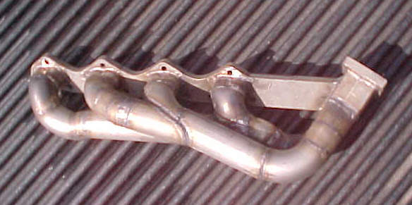